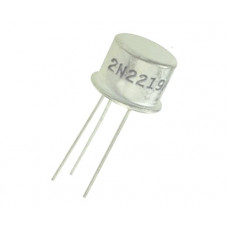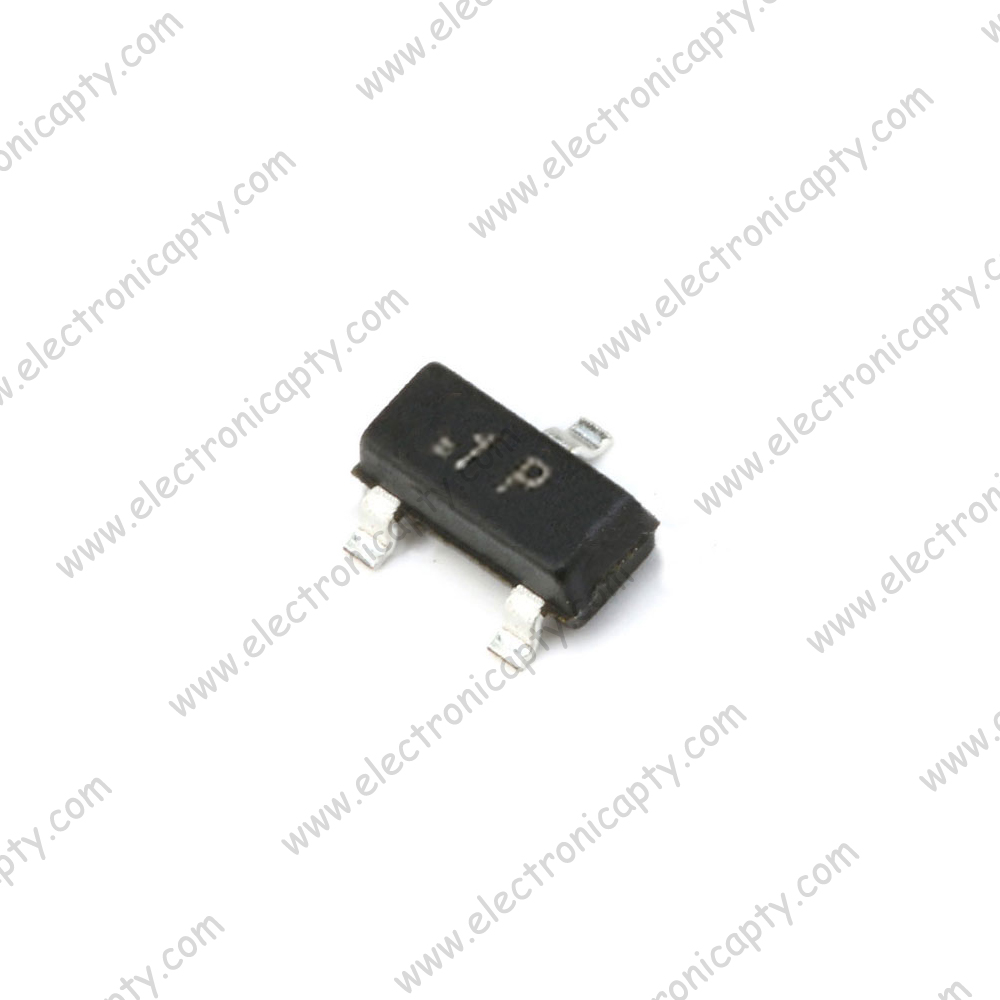
#2n2222 transistor smd code
TC642/TC646/648 TC642EV TC642/TC646/648 TC642EV TC642, TC646 TC648 TC642) TC646/TC648) transistor 2n222a 2n222a npn transistor 2n222a 2n222a datasheet 2n222A TRANSISTOR BDC 47 transistor TRansistor 648 2n2222a SOT23 pin configuration transistor 2N2222A bs170 substituteĪbstract: SMD MARKING CODE C2U SMD MARKING CODE C1G C2U SOT-89 transistor smd 2N4403 c1g smd 2N3904 TRANSISTOR SMD SOT23 transistor 2N2222A RF transistor marking IN SOT-89 2N3640
#2n2222 transistor smd driver
TC642EV-2 2/4/98 S OT-23, driver can be either a SOT, a TO-92 or a T O-220 transistor, depending on the fan operating current and 2, FAULT * Indicates normal value Dashed Line = Factory Setting Figure 1. Text: TC55RP3002EZB 3.0V, 2% regulator Not installed ( S OT-23 site) 2N2222A NPN bipolar transistor Not installed (TO, the factory consists of a 2N2222A transistor and a 1.1K base resistor, which will drive a BDC fan, installed for R2, a 0.1 ♟ capacitor is installed for C5, and a 2N2222A transistor is installed for Q2. The transistor 2N2907 is complementary pair for 2N2222 and has identical specs as above, however being a PNP type the associated polarities are exactly opposite.Sot23 transistor 2n2222a Datasheets Context Search Catalog DatasheetĪbstract: 2n222a npn transistor 2n222a 2n222a datasheet 2n222A TRANSISTOR BDC 47 transistor TRansistor 648 2n2222a SOT23 pin configuration transistor 2N2222A bs170 substitute.

The value of the current limiting resistor may be calculated by using the formula explained at the end of this article.The base goes to the source voltage or the triggering voltage via a current limiting resistor.The load which needs to be switched must be connected in between the collector of the transistor and the positive supply, that is, the positive lead of the load goes to the positive supply while the other lead of the load gets connected to the collector lead of the transistor. The pin out or the leg that’s marked emitter must be connected to the negative line of the supply rail. This may be done by following the below explained steps: Configuring the device practically in electronic circuits for any relevant application:

For a 2N2222A, the figures are 1.2 and 2 volts respectively. With collector current exceeding 500 mA, the base optimal trigger voltage becomes 2.6 volts.


Total power dissipation of the device should not exceed above 500 mW.As expressed earlier, the maximum current that can be applied across the transistors collector and emitter, via a load is not more than 800 mA.With their base open, the above tolerance across their collector and emitter leads is 30 volts for 2N2222 and 40 volts for 2N2222A.The device’s maximum voltage tolerance (breakdown voltage) across its collector and base is 60 volts for 2N2222 and 75 volts for 2N2222A, with the emitters kept open.The transistor 2N2222 or 2N2222A are NPN types and has the following electrical parameters:


 0 kommentar(er)
